
Overview
In this assignment, you’ll explore different ways that the Attractor Logic can be applied to designing features in the built environment.
The common thread in all these applications is that you create a grid of objects, then adjust some property of those objects (for example, their size or height) to reflect the distance between each object and a target point.
For our applications, we’ll use a sine or cosine wave function to add a bit of interest to your designs. So, rather than use a linear relationship to the distance, we’ll set the property that we’re adjusting cycle up and down – similar to the undulating ripples that move across a pond when a pebble is dropped into it.
Steps to Complete
For All Students — A Walk in the Park
Plazas and parks can be much more inviting when we incorporate changes in elevation and surface materials to create smaller, human-scale areas for people to gather, rest, sun bathe, or people watch.
In this exercise, you’ll design a ground surface for a park or plaza with a series of terraces or planted areas with varying heights arranged in a undulating wave pattern.

Using Dynamo

Step 1 – Create of Cuboid Elements
- Create a rectangular grid of points covering an area of about 200’ x 200’ to represent the extents of the park.
- Use an integer slider to give you the ability to change the spacing between the grid points (which will also be the size of the rectangle elements).
- Place Cuboids at each of the grid points to represent the ground surfaces of the park.
- In Dynamo, use the Cuboid.ByLengths node.
- Use each point on your grid as origin of the cuboid.
- Set the width and length parameters to match the size of each grid cell (computed based on your grid spacing).
- The default height of each cuboid is 1, and you’ll change that based on the distance to the attractor point.
Step 2 – Create an Attractor Point to Specify the Center of the Sine Wave Ripple Effect
- Create a point to represent the location that will be the center of the ripple effect.
- Use sliders to control and quickly flex the X and Y coordinates of this point.
Step 3 – Set the Height of Each Cuboid to Simulate the Sine Wave Ripple Effect
- Set the height parameter of the individual cuboid based on the distance between the cuboid’s centerpoint (the grid point) and the location of the attractor point.
- Start by computing the distance between each of the cuboid centerpoints and the attractor point.
- Create inputs (values or sliders) to control the shape of the sine wave effect:
- Number of Waves — the number (or frequency) of waves you’d like to see across the longest distance
- Amplitude — the maximum height of the waves
- Base Height — a base height that will be added to all the computed heights to ensure that all the computed heights are greater than 0.
- Use the computed distance from each cuboid to the attractor point to calculate a height value for each cuboid using the Math.Sine function to simulate undulating ripples.
- An example of a formula that you can use is: baseHeight+(amplitude*Math.Sin((cubeDistance/maxDistance)*360*numberOfWaves));
- Here’s the underlying logic in this formula:
- This formula remaps the distances between each cube and the attractor point to new values between 0 and a multiple of 360 — determined by the number of waves.
- The Math.Sin of these remapped values will be numbers between -1 and +1.
- These numbers are multiplied by an amplitude factor — to make the waves taller - ranging from -1*amplitude to +1*amplitude.
- And these amplified values are added to a base height which you need to set to be bigger than the maximum amplitude value — so all of the computed heights are greater than 0.
Step 4 – Move the Cuboids Up as Needed to Have the Same Base Elevation
- Each cuboid is positioned with its centerpoint in all directions (including the Z direction) at the grid placement point. So as you’ve adjusted the heights, the new height is evenly split above and below the XY plane.
- Compute the distance to raise each cuboid as needed to have all of the bases at the same elevation. This distance will be half of the cuboid height value.
- Use the Geometry.Translate node - using this computed height change as the yTranslation - to create copies of each cuboid at the desired elevation.
- Right-click on the original Cuboid.ByLengths node, and turn off the Preview Geometry checkmark.
For 3 or More Units, also complete — Eliminate the Echo
Spaces with lots of hard, flat surfaces are notorious for reflecting sound waves — creating unwanted echoing and reverberation.
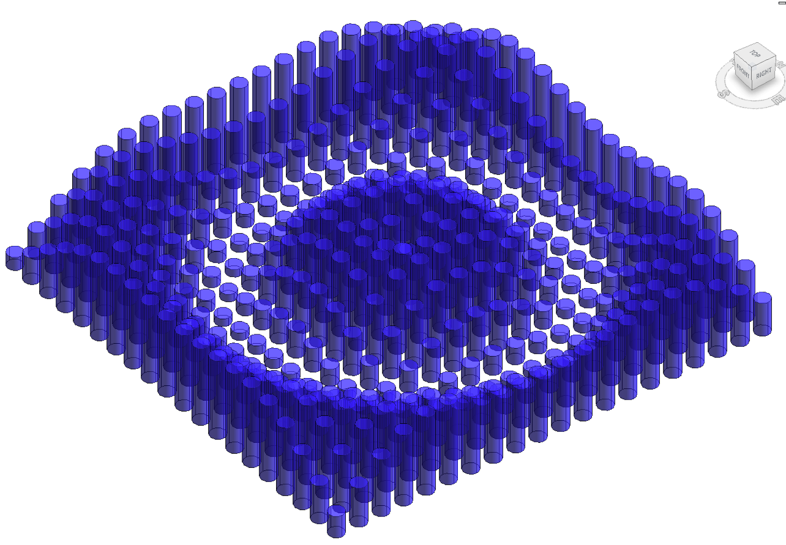
In this exercise, you’ll design a ceiling system of sound attenuating cylinders arranged in a wave pattern, and use an attractor point to specify the center point of the waves.


Using Grasshopper
Use similar Attractor Logic to create a rectangular grid of cylinders that represent an acoustical dampening ceiling in a room — perhaps a recording studio.

Step 1 – Create a Rectangular Grid of Cylinder Elements at the Ceiling Level
- Create an XY Plane to represent the ceiling plane.
- Then use the Move node to move it up to a height of 12’.
- Use the RecGrid node to create a grid of placement points specifying:
- The base plane for the grid (from above).
- The size of the grid cells in the X and Y directions.
- The extends of the grid (number of grid cells) in the X and Y directions.
- Use the Cyl node to create cylinder elements at each placement point specifying:
- The base plane (same as above).
- The cylinder Radius — half of the grid cell size.
- The cylinder Length — use 1 as an initial value, which will be replaced in later steps.
Step 2 – Create an Attractor Point to Specify the Center of the Sine Wave Ripple Effect
- Use the Pt node to create a point to represent the location that will be the center of the ripple effect.
- Use sliders to control and quickly flex the X and Y coordinates of this point.
- Set the Z coordinate to match the height of the ceiling plane.
Step 3 – Set the Height of Each Cylinder to Simulate the Sine Wave Ripple Effect
- Set the height parameter of the individual cylinder based on the distance between the cylinders placement point (the grid point) and the location of the attractor point.
- Start by using the Dist node to compute the distance between each of the cylinder center points and the attractor point.
- Create inputs (values or sliders) to control the shape of the sine wave effect:
- Number of Waves — the number (or frequency) of waves you’d like to see across the longest distance
- Amplitude — the maximum height of the waves
- Base Height — a base height that will be added to all the computed heights to ensure that all the computed heights are greater than 0.
- Use the computed distance from each cylinder to the attractor point to calculate a height value for each cylinder using the Sine function to simulate undulating ripples. You can compute it following these steps:
- Use the Eval node to remap the distance values based on the number of waves that you’d like to appear using formula: pointDistance/maxDistance * 360 * numberOfWaves
- Use the Rad node to convert this number (in degrees) to radians.
- Use the Sin node to compute the Sine values.
- Use another Eval node to incorporate an amplification factor and a base height to ensure all the cylinders have a positive length.
- Use another Eval node to multiple these lengths by -1 (since you’ll want the cylinders to project below the ceiling plane.
- Use the ScaleNU node to scale the cylinders in the Z direction specifying:
- Geometry — the cylinders to be scaled.
- Plane — the base plane from above.
- Scale Z — the scaling factor computed using the Sine wave.

Step 4 – Hide the Unscaled Cylinders
- Right-click on the original Cyl node, and turn off the Preview checkmark.
For 4 Units Only, also complete — Put on a Happy Facade
Attractor point patterns are often used to create patterns in facades or screens. These examples show attractor point patterns being used to determine the attributes of individual panels on a wall surface.


In this exercise, you’ll be exploring how to use the attractor point pattern to adjust a grid of circular openings in a wall.


Using Revit and Dynamo
Step 1 – Open the Revit and Dynamo Files
- Download the files in this Google Drive folder to your computer.
- Open the Revit project file — Happy Facade - Start.rvt.
- Then, open the Dynamo application and File > Open the Dynamo script file - Happy Facade - Start.dyn.

Step 2 – Adjust the Revit Wall Length and Height
- Use the Wall Length and Wall Height sliders to adjust the Revit wall to your liking.
Step 3 – Add Attractor Logic to Adjust the Size of the Circular Openings
- Add two Geometry.DistanceTo nodes to compute the distances between each attractor point and the list of circular opening placement points.
- Use the Math.Min node to find the smallest distance (to the nearest attractor point) for each of the circular openings.
- Use a Code Block to enter a formula that will compute the desired diameter of each circular opening based on its distance from the nearest attractor point. One example is: minDiameter+(amplitude*Math.Cos((distanceToAttractor/maxDistance) * 360 * numberOfWaves));
- Provide inputs for:
- distanceToAttractor — this is the computed distance to the nearest attractor point.
- maxDistance — this should be computed from the Wall Length and Wall Height.
- numberOfWaves — how many wave cycles you’d like to see across the maxDistance.
- amplitude — this scaling factor will amplify the Math.Cos function results (which vary from -1 to +1) and determine the maximum size of the openings.
- minDiameter — this is the smallest size of an opening. It should be at least as big as the amplitude, so you can set a fixed number or even better use a formula to relate it to the amplitude — something like amplitude + 0.1.
- Create a Watch node that displays the results of your new opening diameter calculation.
- Check the results displayed in the Watch node to be sure that all of the computed diameter values are greater than zero.
- Connect the output of your new Watch node to the value input of the existing Element.SetParameterByName.
- Also connect the output of your new Watch node to the computedDiameter input of the existing Code Block in the Display Circles in Dynamo group.


Step 4 – Adjust your New Inputs to Create a Pattern that You Like
- Adjust your new input values and sliders to explore the impact of these changes on the resulting pattern of circular openings.
- When you find a pattern that you like, take a screenshot of the Revit window and submit this in your Notion posting.


Submit
- Please create a folder named “Module 2” within your personal folder in our Autodesk Construction Cloud project.
- Then, upload these items to your Module 2 folder using the web interface:
- For Dynamo projects
- Your Revit project (.rvt) file and your Dynamo script (.dyn) file
- For Grasshopper projects
- Your Grasshopper script (.gh) file
- 4units_SampleStudent_Module2_Walk in the Park.rvt
- 4units_SampleStudent_Module2_Walk in the Park.dyn
- 4units_SampleStudent_Module2_Eliminate the Echo.gh
- 4units_SampleStudent_Module2_Happy Facade.rvt
- 4units_SampleStudent_Module2_Happy Facade.dyn
- Create a link to your Module 2 folder:
- Right-click on the Module 2 folder in the file tree (at the left side of the interface) and choose Share from the pull-down menu.
- Choose Share with Project Members, then switch to the Link tab.
- Click the Copy button to copy the link to your clipboard.
- Create a new posting on this Notion page — Design Journal Entry: Laws of Attraction — that includes a brief overview of each of the models you’ve created. Each project overview should include:
- A screenshot of your finished model geometry
- Walk in the Park - an image of the Dynamo geometry
- Eliminate the Echo - an image of the Rhino geometry
- Happy Facade - an image of the Revit wall
- A few sentences describing your modeling approach
- The link to your Module 2 folder in our Autodesk Construction Cloud project.